Ultraviolet light irradiation

Microorganisms including disease-causing bacteria are killed, or the DNA of the organisms is significantly damaged when exposed to an adequate fluence or dose of ultraviolet (U.V.) light. This fluence is defined by the period and intensity of the exposure of ultraviolet radiation of the proper wavelength, typically between 240 and 280 nanometers (nm).
Keep in mind that when U.V. light is discussed, the term “sterilization” is often used. There is a difference between U.V. light being used for the sterilization or disinfection of water and the use of U.V. light to reduce bacterial numbers and control pathogens in aquaculture production systems. In many cases, while the latter may be possible and desirable, the former may not be economically achievable beyond small hatchery-, nursery- or laboratory-scale systems.
Bacterial load
With that said, ultraviolet light is often considered the process of choice to reduce bacterial loads within the water and water columns of production recirculating aquaculture systems (RAS). The most important factor for U.V. light to work effectively in aquaculture is that the water should have low turbidity and particulate content, and high U.V. transmittance (UVT).
UVT is measured as a percentage of 254-nm light applied through a 1-cm sample of water. A high UVT, such as 90 to 95 percent, indicates the transmittance is high, and the water clarity is good. Therefore, the applied U.V. radiation will have the desired impact on the bacterial population residing in the water.
Accordingly, water within the system should be exposed to U.V. light where the water is most free of suspended and dissolved solids that cause a reduction in UVT. In RAS and other aquaculture systems, the component that supplies U.V. radiation should be downstream of all other water-clarifying processes. The ultraviolet light source would therefore be positioned after solids-removal equipment such as drum screen filters, bead filters, foam fractionators and even ozone contactors.
In fact, when ozone is utilized in aquaculture, its application typically improves the water’s UVT by several percent, thereby enhancing the U.V. process. Following the ozone process with U.V. also serves the purpose of destroying residual ozone before it has a chance to find its way back to the culture tank, where it can harm the cultured organisms.
Lethal dose
While the effective dose of U.V. is largely influenced by the UVT, the lethal dose also depends on the target organism. There are numerous comprehensive reviews of the dose of U.V. radiation required to kill bacteria, viruses, mold spores and yeasts. An example can be found at www.emperoraquatics.com/harmful-waterborne-pathogens.php#pathogen-uv-doses. U.V. light components are marketed to provide a given dose of U.V. light at a specific flow rate and UVT.
Typically, manufacturers categorize units based on effective doses measured in millijoules per square centimeter (mJ/cm2) or micro-watt seconds per square centimeter (µ-Ws/cm2) at a given flow rate and UVT. You can convert millijoules to micro-watt seconds by multiplying by 1,000. These U.V. dosages are calculated at the end of lamp life to guarantee adequate disinfection when systems’ lamps are at their lowest output.
A common lamp type/style used for U.V. disinfection in RAS is “low-pressure/high-output.” These lamps are also known in the industry as amalgam lamps. Their end-of-life rating is typically 80 percent of the initial new lamp output at 12,000 hours. These lamps convert, on average, 35 to 40 percent of their electrical input watts to usable UVC disinfection watts. As a result, on an electrical consumption basis, they are an economical lamp to operate in RAS applications.
The effective U.V. dose listed by the manufacturer can be affected by altering the rate of flow. That is, the U.V. dose is inversely proportional to the flow rate. For example, the dose rate can be doubled by cutting the flow past the U.V. light source in half.
Light components

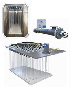
U.V. light components come in two basic formats, the more common being the pressurized “tube-in-shell” design. In this design, water is pumped under pressure past the U.V. lamps, which are isolated in clear quartz sleeves, into the unit’s vessel or shell. These units are made of materials ranging from plastic to various grades of stainless steel, depending upon the pressure requirements of the system and the liquid being processed.
The tube-in-shell units are typically used in systems with flow rates below 7,570 Lpm. The primary application limitations to this design are the need for multiple units if the U.V. dose requirement is high or the UVT is low. Other constraints are the need for proper bypass piping for servicing and the possibility of increased head loss, resulting in additional pumping requirements.
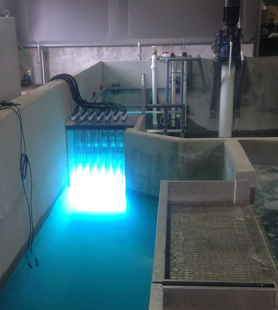
In RAS with high flow rates, high U.V. dose requirements or low UVT, the preferred method is to use a low-head channel U.V. array. In the past, the typical channel array consisted of several lamps spaced evenly in a series of horizontal racks. These were submerged in the water column or channel, through which all the water must pass before returning to the pumping sump or culture tank.
The primary application limitations for the horizontal array design were that the lamp/quartz sleeve sealing mechanisms were fully submerged. This caused durability and reliability issues with the lamps’ electrical connections. These systems also required considerable amounts of maintenance to keep them operational, which substantially increased the cost of ownership.
In recent years, the channel U.V. approach has undergone significant design improvements involving the relocation of the lamps from the horizontal plane to the vertical plane. This dramatically improved the dependability and ease of service, as well as reduced initial capital cost. With the advent of the vertical channel array, it has become more cost effective to employ U.V. light in larger-scale RAS systems.
(Editor’s Note: This article was originally published in the May/June 2014 print edition of the Global Aquaculture Advocate.)
Authors
-

Thomas M. Losordo, Ph.D.
Principal Scientist and Chief Engineer
Aquaculture Systems Engineering
Pentair Aquatic Eco-Systems, Inc.
1791 Varsity Drive, Suite 140
Raleigh, North Carolina 27606 USA[109,111,99,46,114,105,97,116,110,101,112,64,111,100,114,111,115,111,108,46,109,111,116]
-
Don Conwell
Technical Director
Ultraviolet Systems
Pentair Aquatic Eco-Systems, Inc.
Tagged With
Related Posts

Health & Welfare
A comprehensive look at the Proficiency Test for farmed shrimp
The University of Arizona Aquaculture Pathology Laboratory has carried out the Proficiency Test (PT) since 2005, with 300-plus diagnostic laboratories participating while improving their capabilities in the diagnosis of several shrimp pathogens.

Aquafeeds
A look at phospholipids in aquafeeds
Phospholipids are the major constituents of cell membranes and are vital to the normal function of every cell and organ. The inclusion of phospholipids in aquafeeds ensures increased growth, better survival and stress resistance, and prevention of skeletal deformities of larval and juvenile stages of fish and shellfish species.

Health & Welfare
Biofilter inoculation in recirculating aquaculture systems
Biological filters are essential parts of recirculating aquaculture systems that transform toxic fish compounds such as ammonium and nitrite into less-harmful nitrate. The authors tested the convenience and efficiency of three methods for the initial inoculation of aerobic biofilters.

Aquafeeds
A look at protease enzymes in crustacean nutrition
Food digestion involves digestive enzymes to break down polymeric macromolecules and facilitate nutrient absorption. Enzyme supplementation in aquafeeds is a major alternative to improve feed quality and nutrient digestibility, gut health, compensate digestive enzymes when needed, and may also improve immune responses.


