Ammonia-, nitrite-nitrogen concerns; biofiltration

In the November/December issue, this column reviewed important unit processes in recirculating aquaculture system design and began to discuss components used to remove waste solids from the process water. This article explains the importance of controlling ammonia and nitrite-nitrogen concentrations and some of the processes and components used to do so.
Ammonia-, nitrite-nitrogen
Total ammonia-nitrogen (TAN), the combination of un-ionized ammonia and ionized ammonia, is a by-product of the metabolism of protein in aquaculture feed. The un-ionized form of ammonia-nitrogen is very toxic to most finfish. The fraction of TAN in the un-ionized form depends largely upon the pH and temperature of the water. At a pH of 6.8 to 7.2, the majority of TAN is in the ionized form, while at a pH of 8.75, nearly 30 percent of TAN is in the toxic un-ionized form.
The lethal concentrations of ammonia-nitrogen for many species have been established, but sublethal effects are not well defined. Reduction in growth rates may be the most important sublethal but unquantified effect. A good rule of thumb is that the concentration of un-ionized ammonia-nitrogen in tanks should not exceed 0.05 mg/L.
Nitrifying bacteria in production systems use ammonia-nitrogen as an energy source for growth and produce nitrite-nitrogen as a by-product. The nitrifying bacteria grow on the surfaces of biofilter substrates, although all production component surfaces have these bacteria present to some extent.
While nitrite-nitrogen is generally not as toxic as ammonia-nitrogen, it can be very harmful to some cultured species and must be controlled within culture tanks. The toxicity of nitrite-nitrogen is species-specific. For example, while tilapia are highly tolerant of nitrite-nitrogen in the water, hybrid striped bass have a very low tolerance. In freshwater systems, it is a common practice to increase the chloride concentration of the culture water to help reduce the toxicity of nitrite-nitrogen.
Fortunately, other types of nitrifying bacteria (generally referred to as Nitrobacter) are also present in biological filters that utilize nitrite-nitrogen as an energy source. The end product of complete nitrification is nitrate-nitrogen, a relatively non-toxic form of inorganic nitrogen.

Biofiltration processes
Controlling the concentrations of un-ionized ammonia-nitrogen and nitrite-nitrogen in culture tanks is a primary objective in the design of recirculating aquaculture systems (RAS). Ammonia- and nitrite-nitrogen must be removed from the culture tank at a rate equal to the rate of production to maintain a safe concentration.
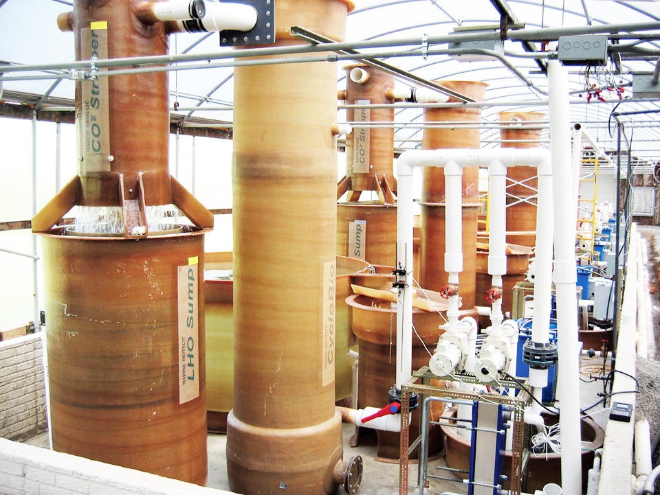
While a number of technologies are available for removing ammonia and nitrite-nitrogen from water, biological filtration is the most widely used in RAS. In the biofiltration process, the substrate has a large surface area, where nitrifying bacteria attach and grow. As previously noted, ammonia-nitrogen in the recycle stream is oxidized to nitrite and nitrate-nitrogen by nitrifying bacteria.
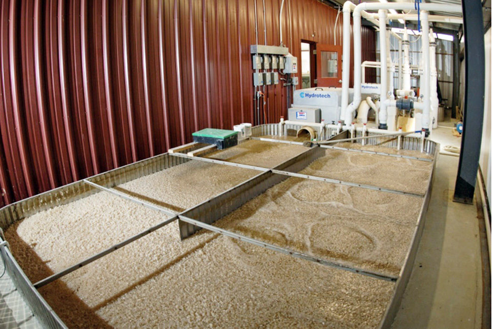
Gravel, sand, plastic beads, plastic rings, plastic tubes and plastic plates are commonly used as biofiltration substrates. The configuration of the substrate and the manner in which it comes into contact with the process water defines the water treatment characteristics and capabilities of the biological filtration unit. Many biofilter components and configurations are available.
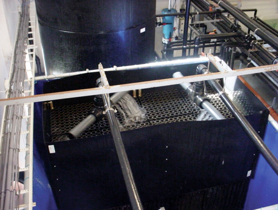
Trickling filters
One of the primary configurations is trickling filters. Used in RAS, these filters evolved from those used in domestic sewage treatment. While they provide one of the simplest forms of biofiltration, trickling filters have provided a reliable unit process for decades. This type of filter consists of a water distribution system at the top of a reactor filled with a media that has a relatively low specific surface area – the surface area within the filter media to be inhabited by the bacteria – generally less than 330 m2/day/m3/day.
Trickling filters are operated in a non-flooded configuration. Low specific surface areas create large air spaces within the filter medium. As such, trickling filters are larger in size than other biofilters of similar capacity. However, as well as reliable nitrification, trickling filters provide aeration and some carbon dioxide removal all in one unit.
Volumetric nitrification rates of approximately 90 g TAN/m3/day biofilter media/day can be expected in warmwater applications with this type of biological filter. When designing these filters for a recirculating system, assuming that 3.5 percent of the feed becomes TAN, a design criterion of 2.6 kg feed/day/m3/day media should be used.
Fluidized bed filters
Fluidized bed filters are essentially sand filters operated continuously in an expanded backwash mode. Water flows up through a bed of sand at a rate sufficient to lift and expand or fluidize the sand and keep the particles in motion so they no longer are in continuous contact with each other. Fluidized bed filters use low-cost sand of smaller diameter than that used in particulate solids removal applications. A fluidized bed filter is an excellent environment for the growth of nitrifying bacteria that can colonize the entire surface area of the filter medium.
Sand used as media in fluidized bed filters has an extremely high specific surface area in excess of 5,000 m2/m3/day. As such, the main advantage of fluidized bed technology is high nitrification capacity in a relatively compact unit. The sand media also is extremely low cost when compared to other plastic media used in biofiltration.
Fluidization (pumping) requirements depend upon the size and weight of the media used. Keep in mind that the buoyancy of the media changes with the amount of biological growth on it. This, in turn, depends upon the water temperature, nutrient loading rate and degree of bed fluidization. Unless there is a system for recovering sand as water leaves the filter, the sand media will need to be replaced.
While fluidized bed filters require energy to keep the sand bed fluidized, their small “footprint” and associated high capacity can be huge advantages. However, fluidized bed filters can become unstable in warmwater systems where high concentrations of dissolved organic nutrients occur. So while they are powerful biofilter reactors, care must be taken in their operation.

Moving bed reactors
Moving bed reactors (MBRs) are an interesting cross between up-flow fixed bed bead filters and fluidized bed sand filters. These filters use plastic media kept in a continuous state of movement, usually with aeration. The diameter of the plastic media is much larger than that of sand, so the media has a lower specific surface area than sand of 450-850 m2/m<sup>3</sup>.
The media pieces are usually neutrally buoyant or just slightly lighter than water. With a coating of bacteria, the media becomes slightly negatively buoyant. Placed within an open top reactor vessel, the biofilter media is mixed with air or water.
Moving bed filters can be designed as up-flow or down-flow filters based on the required system configuration. Depending upon the nutrient concentration, water temperature and salinity, design nitrification rates should range 350-500 g TAN/m3/day. Assuming that 3.5 percent of the feed becomes TAN, a biofilter design criterion of 10-14 kg feed/day/m3/day filter media should be used. Given that MBR vessels can be designed to be deep rather than long or wide, the reactor can have a large volume with a small footprint.
These filters can run with very little head loss across the reactor (usually 10 to 20 cm) and hence require very little pumping energy to operate. Typical installations direct the effluent from a screen filter component by gravity to the MBR. Water is usually pumped from the effluent side of the MBR or from a pumping sump to the next process, which is usually oxygenation and/or ultraviolet sterilization. The main advantages of the MBR design are its compact size, low energy requirements and relatively stable nitrification process.
(Editor’s Note: This article was originally published in the January/February 2014 print edition of the Global Aquaculture Advocate.)
Author
-

Thomas M. Losordo, Ph.D.
Director
Aquaculture Systems Engineering
Pentair Aquatic EcoSystems, Inc.
1791 Varsity Drive, Suite 140
Raleigh, North Carolina 27606 USA
Tagged With
Related Posts

Responsibility
A look at unit processes in RAS systems
The ability to maintain adequate oxygen levels can be a limiting factor in carrying capacities for RAS. The amount of oxygen required is largely dictated by the feed rate and length of time waste solids remain within the systems.

Innovation & Investment
Estimating biofilter size for RAS systems
Controlling total ammonia-nitrogen (TAN) concentrations is the primary concern when sizing a biofilter for use in a recirculating aquaculture system. Sizing decisions are best based on previous experience with a given biofilter media in a specific biofilter configuration.

Aquafeeds
Biofloc and clear-water RAS systems: a comparison
This study compared two types of indoor, shrimp culture systems: clear-water RAS and biofloc systems. Clearwater RAS had the edge in water quality, but shrimp in the biofloc treatment had a higher feed conversion ratio.

Responsibility
A look at various intensive shrimp farming systems in Asia
The impact of diseases led some Asian shrimp farming countries to develop biofloc and recirculation aquaculture system (RAS) production technologies. Treating incoming water for culture operations and wastewater treatment are biosecurity measures for disease prevention and control.

